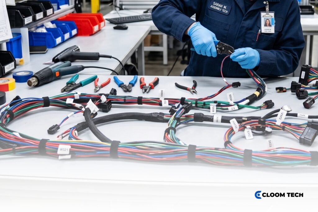
A cable harness assembly can pass an electrical test and still contain workmanship defects that appear in service. You see that gap when a unit matches its schematic during bench testing but loses reliability under heat or vibration. Material choice and termination quality determine whether the finished assembly matches your drawing and operating conditions.
We assess custom wire harness assembly quality against specified materials and documented workmanship criteria. Inspection records tied to the lot show how the build performed against those requirements. Crimps and soldered terminations need visual acceptance plus measurements from the drawing and terminal specification.
Quality evaluation throughout the manufacturing process centers on the objective evidence collected at each production stage.
Materials Selection for Quality Cable Harness Assembly
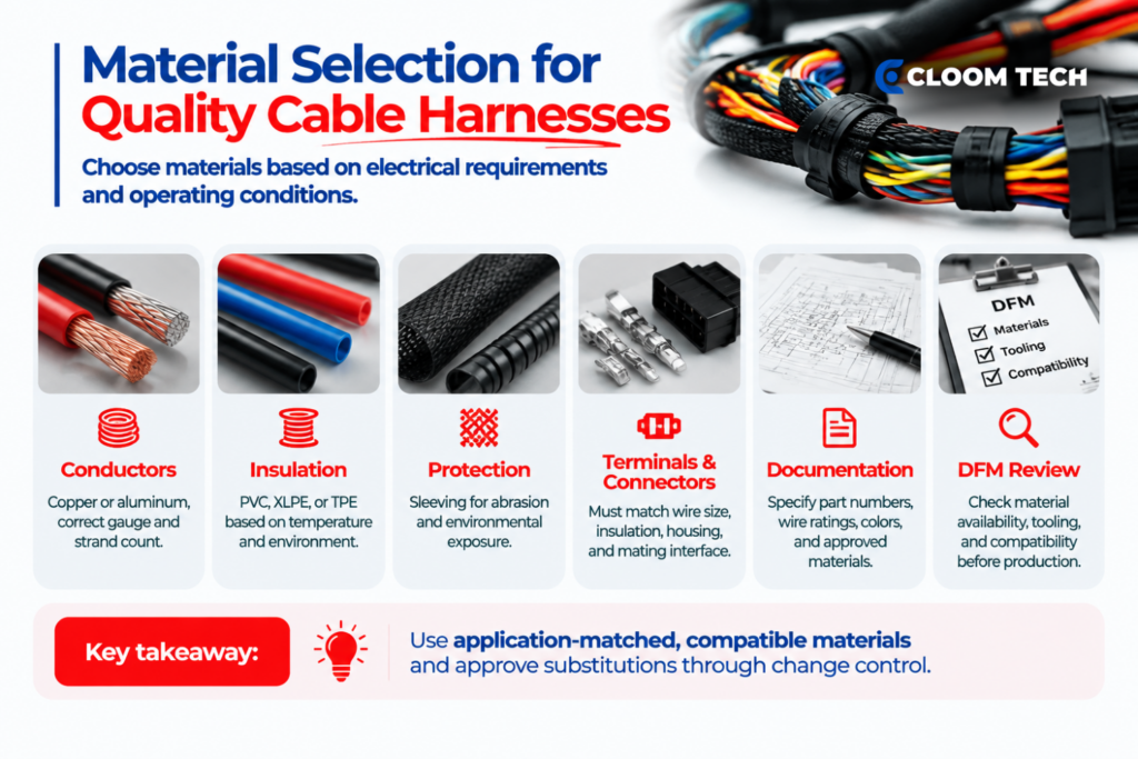
Material selection begins with the electrical requirements and operating conditions documented in your approved drawing package. Exposure to heat, moisture, chemicals, or repeated movement can change which conductor and insulation materials remain suitable during service.
Match conductors and insulation to the application
Conductor size must carry the specified current within the permitted voltage drop and temperature rise. Conductor construction affects flexibility and determines how the wire responds to compression inside the terminal barrel.
Your drawing package should define the material attributes that incoming inspection will verify:
- Conductor material: Copper provides high conductivity for compact conductor sizes, whereas aluminum reduces weight but requires compatible terminals and processing.
- Conductor size: The specified gauge must carry the required current within the voltage drop and temperature limits established for the application.
- Wire construction: Strand count affects flexibility and the way the conductor fills the terminal barrel during crimping.
- Protective covering: Sleeving or another covering must provide the abrasion resistance or environmental protection required by the drawing.
Common insulation materials provide different performance attributes under operating conditions:
- Polyvinyl chloride (PVC): General-purpose PVC wire styles can carry temperature ratings up to 105°C, with the approved wire style establishing the exact limit.
- Cross-linked polyethylene (XLPE): XLPE provides resistance to heat, oil, and environmental stress for applications requiring a more durable insulation system.
- Thermoplastic elastomer (TPE): Some TPE grades retain flexibility during repeated movement, making the specified compound and wire rating important to material approval.
Your approved wire style establishes the applicable temperature and voltage ratings for the finished assembly.
The bill of materials should identify the wire style and conductor size, together with the required color or marking. Incoming inspection can compare the manufacturer’s part number and lot identification with controlled purchasing records.
General descriptions such as “equivalent wire” leave material attributes open to interpretation during purchasing. A proposed substitution should enter the customer’s change-control procedure before the alternative material reaches production.
Specify compatible terminals and connectors
Terminal compatibility depends on conductor material and strand construction, as well as the insulation diameter supported by the terminal. The terminal application specification identifies the approved wire range and tooling required to form the connection.
Connectors are specified by part number on the customer’s drawing and used only inside the completed assembly. Component approval should address four compatibility points:
- Wire-to-terminal compatibility: Approved conductor material and cross-sectional area must fall within the range specified for the terminal.
- Insulation-to-terminal compatibility: Supported insulation diameter must fit the terminal without entering the conductor-crimp area.
- Terminal-to-housing compatibility: Each contact must lock into the specified cavity and maintain its required orientation inside the housing.
- Connector-to-mating-part compatibility: Housing geometry must match the intended interface, including required polarization, sealing, or retention features.
A contact may fit inside a connector housing without supporting the specified conductor or crimp geometry. Terminal plating must remain compatible with the mating contact and operating environment documented for the assembly.
Any proposed connector or terminal replacement requires customer approval because a component change can affect mating fit, retention, or electrical performance.
Use drawing-based manufacturability feedback
Drawing-based manufacturability feedback examines the customer’s existing specification before materials enter production. Our review can identify discrepancies that would interrupt production or prevent repeatable assembly.
Common findings within an existing drawing package may include:
- Terminal range: Selected terminals may not support the specified conductor construction or insulation diameter.
- Connector information: Listed part numbers may conflict with the required mating interface or cavity arrangement.
- Material availability: An approved alternative may satisfy the documented requirements when the original material has limited availability.
- Tooling compatibility: Required tooling may be incompatible with the selected terminal or stated termination method.
Material recommendations may support cost control when an approved alternative satisfies the existing product requirements. Production feedback can identify specifications that add unnecessary handling or reduce manufacturing efficiency.
Every recommendation remains within the customer’s documented product definition and follows the applicable drawing-change procedure. You retain approval authority over each proposed revision before releasing the updated drawing package for manufacturing.
Workmanship Standards for Crimping and Termination Quality
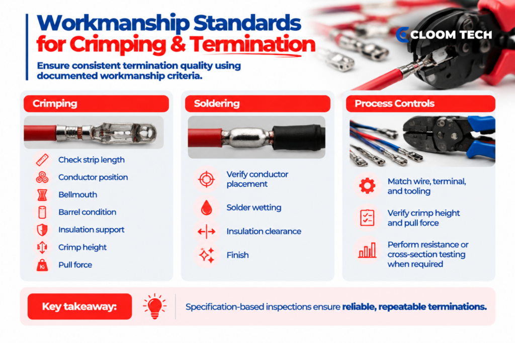
Documented workmanship requirements give our operators and inspectors objective criteria for accepting or rejecting each termination. We use visual inspection to identify external defects, whereas dimensional or mechanical testing evaluates conditions that appearance alone can’t confirm.
Define acceptable crimp quality
Acceptable crimp workmanship begins with conductor preparation that meets the strip-length requirement without excessive strand damage. Incorrect strip length can leave conductor strands outside the intended crimp zone or prevent full insertion into the terminal barrel.
We apply the applicable crimp workmanship criteria covering barrel fill, conductor brush, bellmouth, and insulation support. Our inspection addresses four visible features:
- Conductor position: Stripped conductors must enter the barrel fully without extending beyond the permitted brush length.
- Bellmouth formation: Barrel edges must form within the applicable limits without cutting or pinching conductor strands.
- Barrel condition: Compressed metal must remain free from cracks or deformation prohibited by the controlling specification.
- Insulation support: Support wings must hold the wire without placing insulation inside the conductor-crimp area.
Crimp height measures the compressed conductor barrel at the location defined by the terminal manufacturer. The measured result must fall within the range established for the approved wire, terminal, and applicator combination.
Pull-force testing measures how much force the crimped conductor withstands before separation or failure. The applicable minimum comes from the controlling standard or terminal specification for the approved component combination.
Apply solder acceptance criteria
Acceptable soldered terminations require conductor placement and solder wetting that meet the specified workmanship criteria. Inspection covers the physical conditions that continuity testing cannot verify:
- Conductor placement: Strands must remain in the position required by the drawing and termination specification.
- Solder wetting: Applied solder must wet the required surfaces and form the connection described by the acceptance criteria.
- Insulation clearance: Covering must maintain the required distance from the soldered area without prohibited heat damage.
- Post-solder condition: Finished terminations must remain free from loose strands or residue prohibited by the approved cleaning requirements.
We use the approved soldering instruction to identify the materials and temperature controls required for the termination. Any cleaning step must follow the documented requirements assigned to the approved flux and soldering materials.
Keep measurements specification-based
Crimp-height limits depend on the terminal barrel and conductor construction used in the assembly. Two conductors with the same American Wire Gauge (AWG) size can require different setups when strand count or insulation diameter changes.
Before releasing a crimping operation, our production technicians verify the setup against the terminal application specification:
- Approved wire and terminal part numbers match the released bill of materials.
- Assigned applicators or hand tools match the terminal manufacturer’s tooling requirement.
- Recorded crimp height falls within the range assigned to the approved component combination.
- Required sample pull results meet the minimum established by the controlling specification.
Crimp-height measurement and sample pull testing commonly support setup approval or first-article verification. The customer’s inspection plan determines whether a tooling change or defined production interval requires another measurement.
Electrical resistance testing can support setup validation when the specification requires contact-resistance verification. Cross-section analysis exposes strand distribution, internal voids, and barrel deformation during first-article approval or process validation.
Your drawing or control plan must define the frequency for resistance testing and destructive cross-section analysis. We don’t normally use either method as an every-unit production check.
IPC/WHMA-A-620 as the governing standard
IPC/WHMA-A-620 governs workmanship when the customer specifies the applicable revision and class in the contract, purchase order, or drawing. The documented requirement gives production personnel and inspectors a shared acceptance reference.
Specify the revision and class
The IPC/WHMA-A-620F requirements address cable and wire harness workmanship from wire preparation through final inspection. Its coverage includes:
- Wire preparation criteria for allowable strand damage and conductor deformation after insulation removal.
- Termination criteria for crimped connections and soldered joints under the specified workmanship class.
- Connector criteria for hardware mounting, contact installation, and connector integrity.
- Assembly criteria for securing methods and protective coverings where they apply.
- Inspection provisions for visual examination and specified electrical or mechanical test methods.
Many workmanship features receive stricter acceptance limits as the class increases, although some criteria remain identical across all three classes. The applicable criterion for each inspected feature determines whether the condition is acceptable, a process indicator, or a defect.
- Class 1: General electronic products permit the broadest workmanship variation under the applicable acceptance criteria.
- Class 2: Dedicated-service products apply tighter limits to many workmanship features where continued performance and extended service matter.
- Class 3: High-performance products apply the strictest limits to many termination conditions where performance on demand remains necessary.
The specific A-620 criterion determines whether an acceptance limit changes between classes for the feature under inspection.
Product class establishes workmanship acceptance strictness without defining the assembly’s electrical load or environmental performance. Your drawing and application specifications continue to govern those requirements.
You should identify the complete revision and Class 1, 2, or 3 requirement before the first article inspection. When the user leaves the class unspecified, IPC/WHMA-A-620 allows the manufacturer to select one.
Separate quality systems from workmanship criteria
ISO 9001 establishes requirements for a quality management system. It demonstrates that the audited organization operates documented controls for managing processes, corrective action, and continual improvement within the scope and locations listed on the certificate.
IATF 16949 builds on ISO 9001 with additional requirements specific to automotive supply chains, covering areas such as product safety, process control, and customer-specific obligations from individual OEMs. Their certificates confirm organizational controls, not the quality of any individual assembly.
IPC/WHMA-A-620 provides acceptance requirements for workmanship found in individual assemblies. During supplier qualification, you should confirm four details:
- Each quality-system certificate remains valid for the facility completing your order.
- Documented scope covers the manufacturing activities relevant to your assembly.
- Purchasing documents identify the workmanship standard governing the build.
- Lot-specific records document the inspections performed on the delivered assemblies.
Cloom Tech holds ISO 9001, TS16949, IATF 16949, and IPC/WHMA-A-620 certifications for its manufacturing operations. We inspect each build against the IPC/WHMA-A-620 revision and class named in your purchasing documents.
QC checkpoint table by assembly stage
A rigorous cable harness assembly inspection plan assigns a defined requirement and record to each applicable production checkpoint.
| Assembly stage | What inspectors verify | Specification-based pass criteria | Evidence retained |
|---|---|---|---|
| Incoming material inspection | Wire style, conductor size, terminal part number, connector part number, and lot identity | Received materials match the approved bill of materials and purchasing documents | Receiving inspection record and material lot traceability |
| Wire preparation inspection | Cut length, strip length, insulation condition, and visible strand damage | Prepared conductor meets the drawing dimensions and specified workmanship class | In-process inspection record linked to the work order |
| Crimp setup approval | Terminal, wire, applicator, crimp height, and sample pull result where required | Setup matches the terminal application specification and approved inspection plan | Tooling record, setup measurements, and required sample result |
| Termination inspection | Conductor brush, bellmouth, barrel condition, and insulation support | Termination features meet the specified IPC/WHMA-A-620 class and terminal criteria | Workmanship inspection result and defect disposition |
| Connector inspection | Contact position, terminal seating, housing condition, and required retention features | Contacts occupy the drawing-defined cavities and remain fully seated without housing damage | Connector inspection result linked to the assembly lot |
| Electrical testing | Continuity, circuit mapping, shorts, and resistance where required | Tester results match the approved schematic and customer-defined limits | Test record linked to the assembly |
| Final inspection | Dimensions, labels, protective coverings, and required documentation | Finished assembly matches the released drawing, and all required records are complete | Final inspection record and, when required by the customer, certificate of conformance |
For an electrical harness assembly, continuity testing confirms that each conductor follows the required electrical path. The tester compares the finished circuits with the approved schematic to identify open, shorted, or incorrectly routed connections.
Your approved inspection plan must identify whether each requirement applies to every unit, the initial setup, the first article, or a defined lot sample.
The final inspection compares finished dimensions and identification with the released drawing. The inspector then confirms that every record required by the customer’s inspection plan is present before release.
What this means when evaluating an assembly partner
A useful supplier evaluation connects requirements from your drawing package with defined inspection methods and retained production records.
Request objective quality evidence
The QC table shows where each record fits within production. Ask the assembly manufacturer to provide the following evidence for your build:
- Incoming material records: Part numbers and lot identities should connect received components to the approved bill of materials.
- Crimp setup records: Tooling identification and measured crimp height should correspond with the approved terminal application specification.
- Workmanship inspection records: Visual results should reference the acceptance criteria specified for the build.
- Electrical test records: Circuit results should connect the tested assembly with the approved schematic and customer-defined limits.
- Nonconformance records: Documented disposition should explain how the manufacturer controlled an assembly that failed an assigned inspection.
Buyers often look for named customer relationships when assessing relevant manufacturing experience. For example, Cloom Tech has supplied cable assemblies to Honeywell, which gives you a specific relationship to verify during supplier due diligence.
Confirm production capacity and timing
Production quantities can increase without changing the material or workmanship requirements assigned to the approved drawing. Ask how the manufacturer transfers crimp setup records and inspection instructions from prototype production into recurring orders.
Cloom Tech manufactures custom cable assemblies and wire harnesses at facilities in China and the Philippines. We turn approved drawings and bills of materials into production, supported by manufacturability feedback before tooling begins.
Prototype builds typically complete in three to four weeks, with mass production following in four to five weeks depending on material availability and approved manufacturing requirements. Your purchase documents should identify which records must accompany each shipment and how long the manufacturer must retain supporting inspection evidence.
Cable Harness Assembly FAQs
What is the difference between a quality-system certificate and a workmanship standard?
A quality-system certificate covers the controls used to manage manufacturing operations within its stated scope. A workmanship standard provides the acceptance criteria applied to the finished assembly under the contract, purchase order, or drawing.
Can an electrical harness assembly pass continuity testing and still fail workmanship?
Yes, an assembly can pass continuity testing when every circuit provides an unbroken electrical path. Physical defects require separate visual, dimensional, or mechanical inspection under the specified workmanship criteria.
Who decides the IPC/WHMA-A-620 class for a custom wire harness assembly?
The user selects the IPC/WHMA-A-620 class and should record that decision in the contract, purchase order, or drawing before production begins. When the user leaves the class unspecified, the manufacturer may select one.
What should we send so that the material and workmanship review can start?
Your review package should include the approved drawings and bill of materials, accompanied by the approved vendor list and applicable inspection class. Wire styles and terminal part numbers should appear in the controlled documents before material review begins.
Do generic crimp-height or pull-force numbers apply to every assembly?
Applicable crimp-height and pull-force values depend on the specified terminal and conductor construction. The terminal manufacturer’s application specification provides the controlling limits unless customer documentation establishes another requirement.
What questions expose a weak assembly partner before you place the order?
Ask the manufacturer to provide an example of its receiving record and crimp setup documentation. You should then request a sample electrical test record and documented nonconformance disposition. Detailed answers should identify the governing specifications, inspection frequency, and retained evidence for your production lot.
Back to Top: Cable Harness Assembly: Materials, Workmanship & Quality Standards