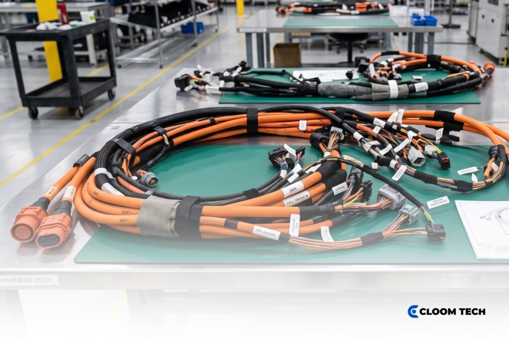
A high-voltage EV wire harness carries traction and charging power between the battery pack, inverter, and other electrically driven vehicle systems. Your harness construction must coordinate conductor size with insulation, shielding, and connector interfaces that match your system’s specified voltage, current, and operating environment.
Orange coverings identify high-voltage conductors outside protected enclosures, giving technicians and emergency personnel an immediate visual warning. The harness may also incorporate a high-voltage interlock loop that monitors loose or disconnected interfaces before the control system permits contactor closure.
For procurement teams, an effective specification connects these safety functions to measurable material requirements, assembly controls, and validation criteria. That connection helps your manufacturer build each harness consistently from your approved drawings.
What does an EV Wire Harness Connect?
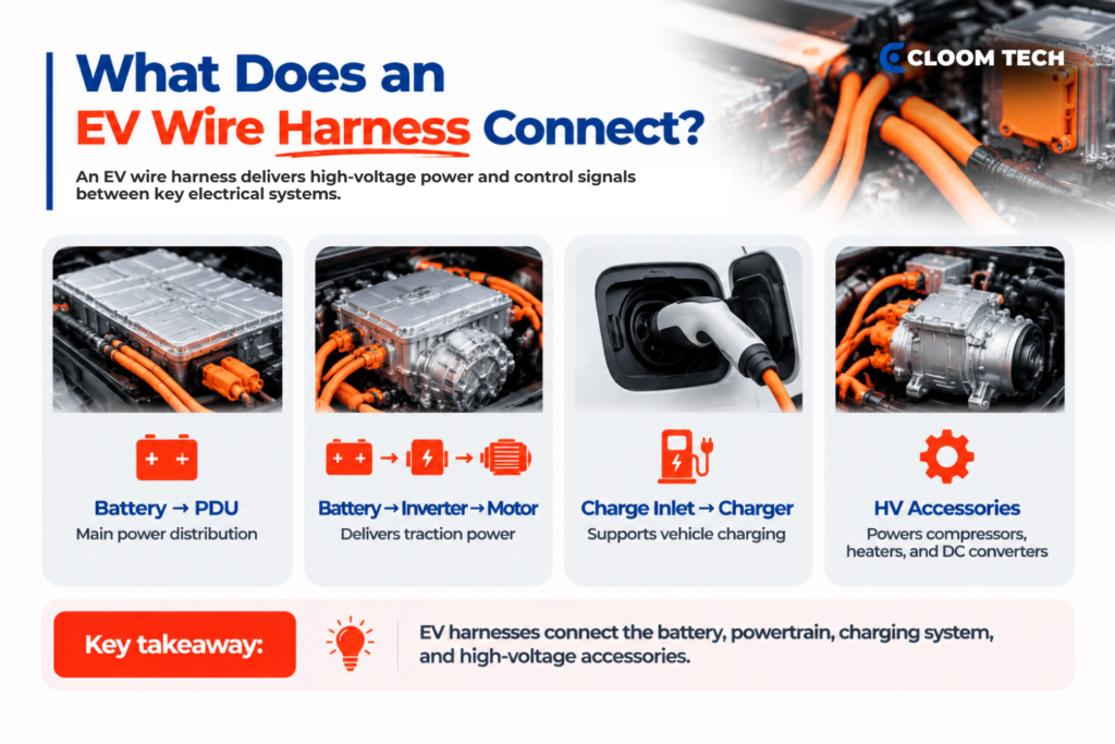
An electric vehicle wire harness connects the high-voltage battery to equipment that handles its power. Separate branches may also carry low-voltage control signals or interlock circuits beside the main conductors.
The principal high-voltage connections usually include:
- Battery pack and power distribution unit: Main conductors carry direct current into the vehicle’s switching and distribution equipment.
- Traction inverter and motor: Shielded conductors deliver power between the battery, inverter, and traction motor.
- Charging equipment: Dedicated paths connect the charge inlet with the onboard charger or battery-side charging circuit.
- High-voltage accessories: Other branches may supply electric compressors, heaters, or direct-current converters.
How do High-Voltage EV Harnesses Differ from Low-Voltage Harnesses?
High-voltage wiring harness construction uses voltage-rated insulation and connection systems, with controlled shielding where required. Low-voltage EV wiring harness branches distribute auxiliary power or control signals under a different load profile, and they’re built to a different standard entirely.
Voltage and current shape cable construction
System voltage changes the current required for a given power level. A 200-kilowatt load draws an idealized 500 amperes at 400 volts or 250 amperes at 800 volts. Lower current can support a smaller conductor, yet 800-volt circuits require higher-rated insulation and interfaces.
Current produces resistive heating in conductors and terminations. Drawings should identify continuous current, peak current, and nearby heat sources. Conductor cross-section also affects the minimum bend radius available for compact routing.
Product-specific conductor cross-section and current ratings
Product-specific conductor cross-sections and current ratings vary with the connector system and its documented test conditions. The table below compares named products at 85°C; the finall selection follows the approved drawing plus supplier derating data. Routing conditions and permitted voltage drop may require a larger conductor.
| Named connection system | Conductor cross-section | Approx. AWG | Connector/system rating at 85°C | Idealized power at 400V | Idealized power at 800V |
|---|---|---|---|---|---|
| TE Connectivity HC-STAK 25 | 50 mm² | Near 1/0 AWG | 247 A maximum | 99 kW | 198 kW |
| Aptiv SHIELDPACK HV AK Class 4 SI, 2-way | 25–50 mm² | About 3 AWG–1/0 AWG | 235 A maximum | 94 kW | 188 kW |
| TE Connectivity HC-STAK 35 | 95 mm² | Between 3/0 and 4/0 AWG | 400 A maximum | 160 kW | 320 kW |
| HUBER+SUHNER RADOX EV-C 2 | 120 mm² | Larger than 4/0 AWG | 452 A current capacity | 181 kW | 362 kW |
Power values multiply published current by the nominal voltage and exclude conversion losses. Continuous and peak current must follow the approved load profile. Ambient temperature and bundling conditions may require a larger cross-section.
Insulation and shielding protect the complete system
Insulation must maintain dielectric separation at the specified voltage and temperature. The jacket protects against stated fluids and wear within the minimum bend radius.
Shielding limits electromagnetic energy from inverter switching that could couple into nearby circuits. A continuous 360-degree screen termination supports the cable-and-connector system. SAE J1742 places electromagnetic evaluation at the system level for the combined assembly.
Why do High-Voltage EV Cables Use Orange Coverings?
High-voltage EV cables use orange coverings to identify conductors connected to a high-voltage source outside an electrical protection barrier. This visible distinction helps technicians and emergency personnel recognize EV wire harnesses before service or emergency work begins.
Federal Motor Vehicle Safety Standard 305 defines high voltage as more than 30 volts alternating current or 60 volts direct current. It requires orange coverings on high-voltage cables outside electrical protection barriers. FMVSS 305a maintains this requirement. It becomes mandatory on Sept. 1, 2027, for covered light vehicles and Sept. 1, 2028, for heavier vehicles. FMVSS 305 remains in effect until a vehicle receives certification under FMVSS 305a.
Orange identifies the circuit category, and your approved drawing provides its electrical limits. Rated components and controlled disconnection provide electrical protection.
How does a High-Voltage Interlock Loop Protect the System?
A high-voltage interlock loop is a low-voltage circuit routed within specified high-voltage connectors and enclosures. A complete loop confirms that monitored interfaces have reached their accepted state before high-voltage power becomes available.
Connector sequencing detects separation before power contacts open
Interlock contacts use a last-mate, first-break arrangement, so auxiliary contacts complete after the power contacts during mating and separate first during unmating. The controller receives the resulting loop change before the main terminals separate, allowing a partially engaged connector to register as a fault. Integrated HVIL functions monitor connection integrity in connector families that provide this feature.
The battery management system uses loop status to control contactors
The battery management system evaluates the returning signal and permits contactor closure after the interlock reaches its accepted state. Precharge can raise downstream bus voltage gradually before the main contactors close.
A loop interruption can keep contactors open or request an orderly transition based on the vehicle’s programmed state, with platform controls defining exact thresholds and responses. Your EV wiring harness must provide the specified interlock circuit and terminal sequence, with resistance remaining within the accepted range.
What Should You Specify When Sourcing an EV Wire Harness Partner?
You’ll need to provide separate technical requirements and commercial documents when sourcing an EV wire harness manufacturing partner for repeatable production.
Technical requirements define the assembly
Your technical requirements document the selected conductor system and every interface your manufacturer must reproduce from the approved drawing.
- Electrical system: Record working voltage and the selected conductor system established from your approved load calculations.
- Cable construction: Specify insulation and jacket requirements, followed by the required shielding and screen-termination method.
- Connector interfaces: Provide connector series and terminal part numbers, including the required seals and mating conditions.
- Mechanical layout: Record branch dimensions and bend limits, with environmental requirements assigned to each installation zone.
- Safety functions: Define interlock routing and terminal sequencing, followed by service-disconnect and touch-protection criteria.
Every harness requirement should match a drawing revision and bill-of-materials entry. Any conductor, terminal, or seal substitution requires your documented approval before production.
Quote-package documents define production inputs
Quote-package documents provide the manufacturing and commercial information needed to price your approved assembly.
- Approved drawing: Provide branch geometry and tolerances, with the current revision identified on every submitted page.
- Bill of materials: List approved manufacturer part numbers for conductors, terminals, connectors, and protective materials.
- Pin map: Identify circuit positions and wire labels, followed by polarity and interlock paths.
- Test plan: State test methods and acceptance limits, including the required sampling frequency and production records.
- Workmanship criteria: Name the IPC/WHMA-A-620 revision and class required by the contract.
- Order profile: Provide prototype quantity and forecast volume, followed by lot size and delivery schedule.
- Change process: Define approval authority for proposed substitutions and drawing revisions.
Which Standards and Tests Apply to High-Voltage Harnesses?
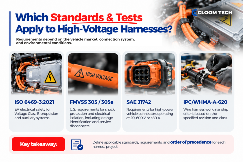
Applicable standards and tests depend on the vehicle market and connection-system scope. Your customer requirements address the assigned environmental conditions.
Standards define different parts of the safety framework
ISO 6469-3:2021 covers voltage class B electrical safety within electric propulsion systems and conductively connected auxiliary systems in electrically propelled road vehicles.
Federal Motor Vehicle Safety Standards 305 and 305a address electric-powertrain integrity and shock protection in the United States. Their requirements cover orange identification, direct-contact protection, service disconnects, and electrical isolation.
SAE J1742 is a stabilized recommended practice for high-power road-vehicle connection systems. It covers connections operating from 20 to 600 volts regardless of current or carrying at least 80 amperes regardless of voltage. Its procedures address in-line and header connectors plus device interfaces through 120 square millimeters or 4/0 AWG. Internal module connections and complete subassemblies fall outside this scope.
IPC/WHMA-A-620 supplies workmanship criteria when the contract invokes a specific revision and class. Your EV wire harness specification should identify each applicable document and establish an order of precedence.
Validation must reflect the specified application
Validation must reproduce the connection system’s assigned conditions. SAE J1742 calls for additional testing when vehicle exposure exceeds documented temperature or vibration limits.
Production verification can include the following controls when your approved test plan requires them:
- Circuit verification: Continuity testing confirms pin-to-pin paths, including monitored interlock circuits.
- Insulation evaluation: Insulation-resistance and dielectric-withstand tests apply the specified voltage and acceptance limit.
- Termination checks: Crimp measurements and pull testing confirm your acceptance criteria.
- Environmental validation: Sealing, vibration, or thermal tests reproduce the defined installation exposure.
Test equipment must match the assembly’s maximum voltage and measurement range. Records should identify the part number, revision, limits, and results, keeping the lot traceable to your approved harness requirements.
EV Battery Wire Harness Design FAQs
Does orange cable color identify the exact voltage rating?
Orange identifies a high-voltage conductor outside a protected enclosure. Printed markings and your approved drawing provide the working voltage and construction details.
Can copper and aluminum conductors use the same high-voltage terminal?
No, not typically. Copper and aluminum conductors require terminals and processes qualified for the chosen material. Contact resistance and environmental validation determine whether the same terminal can support both.
When can a rigid busbar replace a flexible battery cable?
A rigid busbar suits short, fixed connections with controlled alignment. A flexible high-voltage cable accommodates movement between separated equipment.
What changes between prototype and mass-production harnesses?
Mass production adds controlled tooling and lot-level records to the approved prototype configuration. Material or dimensional changes follow your revision process before production begins.
Back to Top: EV Battery Wire Harness Design: High-Voltage Safety & Orange Cable Standards