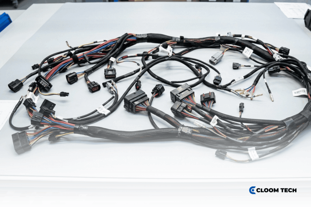
Wire harness components have to match at every connection, from the conductor inside a terminal barrel to the seal around the wire’s insulation. Specifying a connector housing alone, for example, leaves its compatible contacts and retention hardware open, even when the housing matches the equipment’s mating interface.
For procurement teams preparing a request for quotation (RFQ), those relationships decide which part numbers belong together in the specification. Buyers often find that many RFQ clarification rounds trace back to these gaps. Your requirements should also cover protection at exposed routing points and attachment hardware that fits the available mounting locations.
How Wire Harness Components Work Together
Conductors carry power or signals through the assembly, while terminals form the electrical connection at each end. Around those connections, housings locate the contacts and provide the mechanical interface with the equipment.
Protective coverings surround exposed runs, and mounting hardware holds the harness in position along its installation path. Thus, a wiring harness encompasses both the circuit connections and their physical arrangement within the equipment.
In practice, changing one part often affects another. At a panel entry, for example, the bundle must fit both the protective covering and the grommet opening. A thicker covering can therefore require a different grommet, even when the electrical connections stay the same.
Wire and Conductors
Wire specifications define the conductive path and the insulation around it, with construction choices tied to each circuit’s operating requirements. Record these details for each wire, rather than assigning one general specification to the whole harness:
- Conductor size: State American Wire Gauge (AWG) or cross-sectional area, and make circuit current and permitted voltage drop available for review. Comparing wire gauges means weighing run length and installation conditions alongside the electrical load.
- Material and stranding: Identify conductor material and strand construction, plus movement requirements for any branch that bends repeatedly in service.
- Insulation: Specify the wire’s temperature and voltage ratings, then note fluid exposure or abrasion requirements for each installation zone.
- Outside diameter: Include finished wire diameter wherever seals or terminal insulation supports only accept a set size range.
Where circuits join inside the harness, add a splice map showing which wires meet at each splice and where it sits along the branch. Splices are easy to leave off a drawing, yet they directly affect bundle size, sealing, and repair access.
Terminals
Terminals form the conductive connection between a wire and its attachment point, which may sit inside a housing or on the equipment itself. In the terminal specification, identify the exact contact part number and its approved conductor range. A common challenge is a terminal that fits the wire gauge but not the insulation diameter, so its insulation grip can’t support the wire.
For stud connections, include the stud diameter and the space available around the terminal tongue. For separable contacts, specify the required plating and the compatible mating contact, rather than choosing a finish by appearance.
The crimp tooling and wire combination must match the selected terminal, with acceptance limits drawn from the component documentation. Before you approve a terminal substitution, ask the manufacturer to confirm tooling availability and inspection criteria.
Connectors, Seals and Locks
Connector housings position contacts for mating, while seals and locking features handle environmental exposure and mechanical retention at that interface. Comparing connector types helps you settle the connection format before specifying the individual housing system:
- Housings: Provide both mating part numbers and the cavity assignment, with orientation or keying details wherever similar interfaces sit close together.
- Seals: Identify the seal that fits the specified wire diameter, plus cavity plugs where the connector system requires them in unused positions.
- Terminal position assurance: Where the connector system uses terminal position assurance (TPA), the feature supports contact retention and can reveal incomplete insertion.
- Connector position assurance: In systems with connector position assurance (CPA), the feature helps prevent unintended release once the mating halves fully engage.
For sealed interfaces, state the required ingress protection (IP) rating and the conditions under which the connection must meet it. If protection must hold during servicing, not just in the fully mated state, this requirement should be explicitly stated in the specification.
Protection and Routing Components
Protective coverings guard against contact with surrounding surfaces, while routing components protect transitions where the harness crosses an enclosure or leaves a connector. Mark coverage locations on the drawing so protection follows the real exposure along each branch:
- Sleeving, loom, and conduit: Define bundle diameter and required abrasion resistance, plus any access needs that call for a covering that opens along its length. A split wire loom, for instance, lets installers insert wires from the side without threading the whole bundle through a closed tube.
- Tape: Specify backing material and adhesive suited to the operating temperature, with wrap locations and overlap requirements on the drawing.
- Heat shrink: Define expanded and recovered dimensions so tubing slides over the installation point and shrinks onto the intended surface. Where sealing matters, specify adhesive-lined tubing compatible with the underlying insulation and the required overlap.
- Grommets: Provide panel thickness and cutout dimensions, then match the internal opening to the finished bundle diameter at the pass-through.
- Backshells and overmolds: Identify connector exit direction and available installation space, including the required strain relief at terminations.
- Shielding: Specify foil or conductive braid where electromagnetic interference (EMI) control requires shielding, with termination details at each relevant connection point.
Securing and Labeling
Clips and ties hold the harness along its installation route, while labels identify the assembly or individual connection points. Mounting requirements should account for the finished bundle size and the attachment features available on the equipment. This matters most on long branches, where unsupported spans can sag into moving parts.
For clips, provide mounting-hole dimensions and panel thickness, with locations measured from defined drawing reference points. Tie specifications should state material suitability and application tension, so ties control movement without exerting excessive pressure on the insulation.
Label requirements should define the printed content, its position, and a text orientation that stays readable after installation. Where cleaning fluids contact the assembly, request marking materials and print systems that resist those named chemicals.
Wire Harness Parts at a Glance
A complete parts list separates accessories you buy separately from features already included with a selected component. Before adding seals or secondary locks to the bill of materials (BOM), check the supplier’s package contents to avoid missing or duplicate quantities.
| Component | What it is | Specification Question to Ask | Common Failure Point |
|---|---|---|---|
| Wire and insulation | Insulated conductive path | Which construction suits the load and movement? | Strand fatigue or insulation wear |
| Terminals | Conductive end connections | Which contact fits the wire and mating interface? | Loose or damaged crimp |
| Connector housings | Contact positioning bodies | Which mating part and keying apply? | Damaged latch or incorrect keying |
| Seals and plugs | Barriers at connector openings | Which seal fits the finished wire diameter? | Leakage through an incorrect seal |
| TPA and CPA features | Secondary retention features | Which locks does this connector require? | Incomplete lock engagement |
| Splices | Permanent conductor junctions | Which wires join, and where? | Incorrect wire combination in the splice |
| Sleeving, loom, and conduit | Bundle coverings | Which exposure and access requirements apply? | Wear at an unprotected branch exit |
| Tape and heat shrink | Wraps or fitted insulation | Which material and coverage dimensions apply? | Lifted tape or incomplete tubing recovery |
| Grommets | Panel-edge protection | What are the cutout and bundle dimensions? | Dislodgement from poor panel fit |
| Backshells and overmolds | Connector-exit protection | Which exit geometry and support are required? | Concentrated bending at the exit |
| Shielding | Conductive interference barrier | Where and how must the shield terminate? | Discontinuous shield connection |
| Clips and ties | Bundle retention hardware | Which mounting interface and tension apply? | Chafing at an attachment point |
| Labels | Assembly or circuit identification | What must remain readable after exposure? | Faded print or detached label |
What to Include in Your RFQ
Your RFQ should link the assembly drawing to a revision-controlled BOM, with each component identifier traceable between the two documents. Beyond the individual component specifications, include the information a manufacturer needs to interpret and quote the complete assembly:
- Drawing details: Show branch lengths and tolerances, with connector orientation and attachment locations referenced to clearly defined measurement points.
- BOM entries: List manufacturer part numbers and quantities, and identify any components you plan to supply to the harness manufacturer yourself.
- Circuit documentation: Provide the pin-to-pin connection schedule and splice map so the manufacturer can confirm the intended electrical configuration.
- Acceptance requirements: State the applicable workmanship criteria and required tests, plus documentation expectations for sample approval and production deliveries.
- Commercial scope: Include sample quantities, expected order volumes, packaging requirements, and the delivery destination for the quotation.
A complete package is also the fastest route to an accurate quote. When drawings, BOMs, and the connection schedule agree, the manufacturer can price the build without a round of clarification questions.
Turn Your Component Specifications Into a Complete Harness
At Cloom Tech, we review the component requirements in your existing drawings and manufacture customized harnesses to your approved specifications. Connectors, terminals, and every other component go into the finished assembly; we don’t sell them separately. Our DFM feedback can recommend material alternatives and identify ways to reduce assembly costs or improve production efficiency. We don’t create drawings from scratch, so your team approves every specification change before production.
We’re ISO 9001 and IATF 16949 certified and manufacture to IPC/WHMA-A-620. Samples take 3–4 weeks, and mass production takes 4–5 weeks. Send your drawings and bill of materials, including any unresolved component selections, and we’ll review those choices as we prepare your quote.
Wire Harness Components FAQs
Can a manufacturer substitute wire harness parts?
Only with your approval. A manufacturer can propose alternatives where your purchasing requirements allow them, but each change needs review against the approved assembly specification. Record the accepted replacement part number and any required validation before authorizing its use in production.
Should spare connector positions appear in the documentation?
Yes, your cavity map should identify unused positions so the manufacturer can tell intentional spare capacity from an omitted circuit. For future expansion, also state whether the delivered harness needs spare wires or only vacant housing positions.
Can one harness contain different wire gauges?
Yes, a single harness can use different wire gauges when its circuits have different electrical loads or installation requirements. A motor supply branch, for example, may need a larger conductor than an adjacent sensor connection in the same assembly.
How does a wire harness differ from a cable assembly?
A wire harness typically organizes individual wire runs into a defined layout, often with branches serving several connection points. A cable assembly usually uses one or more jacketed cables with fitted terminations, although suppliers use the terms loosely. For quoting, describe the actual construction and connection arrangement rather than relying on the label alone.
Back to Top: Wire Harness Components: The Parts Every Buyer Should Know Before an RFQ