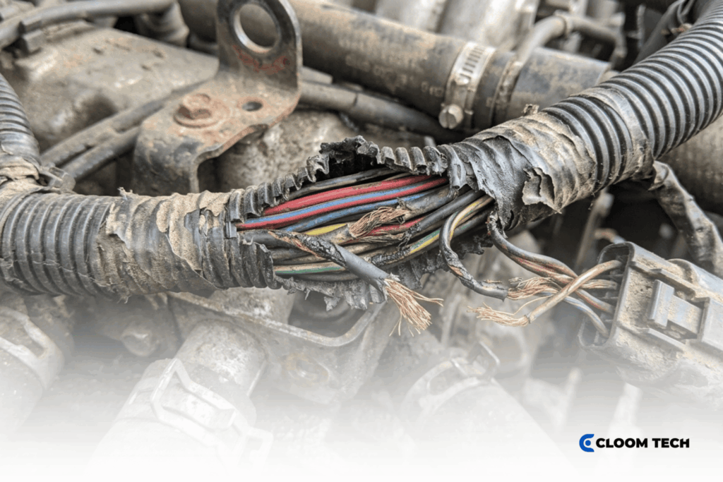
Wire harness failure modes usually start small. Movement wears through insulation, vibration loosens connections, and assembly defects, heat, and moisture weaken joints. A harness can pass end-of-line testing and still fail months later, once mechanical stress or environmental exposure finds the weak point.
Buyers often find that replacing the failed part only resets the clock. A lasting fix connects the damage in your field returns to the operating conditions at that location. It then turns that mechanism into a requirement your manufacturer can verify on the next build.
Why Wire Harnesses Fail
Wire harnesses fail when repeated mechanical loads damage conductors, or when environmental exposure breaks down insulation and electrical contacts. In practice, most field failures trace back to a small set of root causes, so a structured root cause analysis pays off quickly.
Manufacturing defects often leave a joint vulnerable before the harness ever ships. Movement, vibration, heat, or moisture in service then supplies the stress that exposes that weakness. For example, a loose crimp might pass bench testing, then open intermittently once the equipment starts vibrating.
Use wiring fault diagnosis to confirm the electrical fault first. Next, tie the confirmed mechanism to a requirement your manufacturing or validation team can check. Recording it in your FMEA keeps the same risk under review on future builds.
Chafing and Abrasion
Chafing wears through insulation when a harness rubs repeatedly against an edge, bracket, or neighboring component. Once the protective layer is gone, the exposed conductor can short to ground or to an adjacent circuit. On shielded cables, abrasion can also cut through the braid and weaken EMI protection.
The damage usually shows up as flattened or shiny insulation, or exposed copper, at a panel crossing or bracket. That location shows where movement keeps forcing the harness against the same surface. To prevent it, specify these points on your drawing:
- Panel openings: Specify the opening size and grommet retention so the grommet stays seated where the harness passes through the enclosure.
- Protective coverage: Mark sleeve start and end positions on the drawing so production covers the full contact zone.
- Support placement: Define clamp positions along the installed route so movement can’t carry the bundle into an adjacent moving part.
- Assembly restraint: Set tie tension and clamp fit to hold the harness without denting the insulation or creating a pressure point.
Corrosion and Fretting
Corrosion and fretting both raise contact resistance, but they start in different ways. Corrosion is a chemical attack on conductive surfaces, while fretting is mechanical wear from tiny repeated movements between mating contacts. That difference matters because moisture sealing addresses one and mechanical stabilization addresses the other.
Corrosion from environmental exposure
Moisture and contaminants usually reach contact surfaces through damaged, missing, or poorly fitted seals. The connector materials and operating environment then determine how quickly corrosion develops. You may see green or white deposits or degraded plating, although the affected surface often sits hidden inside the housing.
To prevent it, specify contact finishes and seal materials that suit the actual fluids and contaminants in the installation. Then define sealing requirements for every cavity, both populated and unused.
Fretting at the contact interface
Each small movement wipes through the contact plating, and the freshly exposed metal oxidizes. As that oxide debris builds up, contact resistance starts to fluctuate, and tin-plated contacts are especially prone to it. Contacts can still move slightly inside a fully engaged housing, so an intact latch doesn’t prove the connection resists fretting.
Require vibration qualification that reflects the connector’s real installation, including its mounting arrangement and the electrical acceptance criteria used during testing.
Terminal Push-Out and Connector Back-Out
These two failures sound similar, but they happen at different levels of the connection. Terminal push-out moves a single contact backward inside its housing, while connector back-out separates the mating housings themselves. Both reduce contact engagement, and both often appear as intermittent faults rather than a clean open circuit.
Terminal push-out
When the connector halves mate, the mating force can push back a terminal that isn’t fully seated and locked. The result is a recessed contact with reduced engagement, which you can often spot at the connector face. Verify terminal seating and retention against the connector requirements, and record the inspection or push-back test in your production control plan.
Specify compatible terminal and housing part numbers on the drawing. Include any secondary lock the connector system requires, such as a terminal position assurance (TPA) feature.
Connector back-out
Connector back-out happens when the mating housings lose engagement, which loosens every terminal across the interface at once. A partly engaged latch or a visible gap between the housings is the typical sign. Define locking and mating checks for the selected connector, including full engagement, connector position assurance (CPA) where fitted, and any fastener requirements.
For threaded connectors, record the specified torque in the assembly instructions and verify it during inspection.
Vibration Fatigue
Vibration fatigue breaks conductor strands through repeated bending. It concentrates where movement meets a rigid point, such as a termination or an unsupported branch exit. Strands can break beneath intact insulation, so the first symptom is often an intermittent fault before the last strands separate.
At a breakout, the way the branch moves relative to the main bundle decides where bending loads concentrate. Two specification points help control it:
- Movement requirements: Record the expected motion and duty cycle, then select a wire construction with qualification evidence that matches the branch’s installed use.
- Transition support: Specify strain relief methods that move loads away from the termination while still allowing the movement the connector exit needs.
Crimp Defects
Crimp defects weaken the conductor-to-terminal joint when compression or wire preparation falls outside the acceptance criteria for that terminal. Cut strands or insulation trapped inside the barrel can compromise the joint. That’s why a crimp that looks right from the outside isn’t necessarily sound inside.
Under-crimping
Under-crimping leaves too little compression around the conductor. The resulting joint is mechanically weak and can loosen under tension or vibration, often showing up as rising resistance or low pull-out force.
Match crimp tooling and settings to the specified terminal and wire size, then verify crimp height and pull-force results against the acceptance criteria.
Over-crimping
Over-crimping applies too much compression, which can cut or deform strands and crack the terminal barrel. That reduces the conductor area carrying current through the joint. Inspect strand condition against the applicable requirements, and use cross-section analysis wherever your inspection plan calls for an internal check.
If you’re weighing crimp vs. solder for a problem connection, choose the method the connector requires and validate it against the movement in your application. Keep in mind that solder wicking creates a rigid zone where vibration fatigue can start.
Insulation, Heat and Moisture
Insulation failure reduces the separation between electrical paths. Heat and moisture can speed up that breakdown or expose a weakness that was already there.
Thermal degradation
Insulation hardens, cracks, or deforms when its temperature exceeds the material’s rating for long enough. That temperature comes from two sources: ambient heat at the installed location and the heat the conductor generates under load. Define the temperature at the installed location, check conductor loading against it, and set acceptance criteria for cracking or deformation.
Near heat-producing equipment, specify the required clearance or heat shield. Then measure temperatures on the completed assembly to confirm the protection works.
Moisture ingress
Moisture ingress lets water or contaminants reach areas that should stay electrically isolated, causing current leakage or unstable connections. Water can also wick along conductor strands well beyond the point of entry.
Specify wire seals that match the insulation diameter, and list cavity plugs for every unused position in the assembly requirements. Finally, validate the completed interface against the expected exposure, with insulation resistance limits that reflect the leakage risk in your application.
How Do You Match Controls to Wire Harness Failure Modes?
Match each control to the condition that started the damage. Replacing a failed component without changing that condition leaves the original exposure in place, and the failure tends to return. Use this table as a quick reference when you review field returns:
| Failure Mode | Root Cause to Confirm | Prevention Requirement |
|---|---|---|
| Chafing and abrasion | Movement against an edge or adjacent component | Defined clearance and retained protection at the contact zone |
| Corrosion | Moisture or contaminants reach exposed contact surfaces | Compatible contact finishes and complete environmental sealing |
| Fretting | Small repeated movements between mating contacts | Installation-specific vibration qualification and a stabilized contact interface |
| Terminal push-out | Incomplete seating or inadequate terminal retention | Terminal position verification and required secondary locks (TPA) |
| Connector back-out | Incomplete engagement of the mating housings | Locking verification (including CPA) and fastener checks |
| Vibration fatigue | Concentrated bending near a termination or breakout | Movement-compatible wire construction and supported transitions |
| Under-crimping | Insufficient compression around the conductor | Matched tooling settings with crimp height and pull-force checks |
| Over-crimping | Excessive compression damages conductor strands | Strand-condition acceptance and cross-section analysis where required |
| Thermal degradation | Temperature exceeds the insulation’s rating | Temperature-rated materials and validated clearance or heat shielding |
| Moisture ingress | Incomplete or incompatible sealing | Matched wire seals, unused-cavity plugs, and exposure validation |
How to Prevent Repeat Failures
Preventing a repeat failure takes two kinds of evidence. The revised assembly has to withstand the operating stress behind the return, and production has to build it the same way every time.
Connect manufacturability feedback to the failed feature
This is where DFM feedback helps most. At Cloom Tech, we review the drawings your team already owns. We don’t create harness drawings from scratch or take on product development. Instead, our feedback covers material selection, cost reduction, and production efficiency, and your team approves any changes.
Take a conductor fracture near a connector exit. Our review would assess the available bend space and support arrangement against the movement you recorded. Before you submit the revised requirements, it’s also worth checking them against common wire harness mistakes at the quoting stage.
Any material alternative proposed to reduce cost must meet the same movement requirements, and your team should confirm its performance before approving the substitution. Likewise, production-efficiency recommendations should make the corrected support easier to assemble consistently, not remove the feature that fixed the fracture.
Apply workmanship controls to the physical weakness
IPC/WHMA-A-620 workmanship requirements set acceptance criteria for wire preparation and terminations, and manufacturing must apply them at the affected connection. For the fractured conductor example, inspection should check for strand damage during stripping and confirm the specified wire dress at the connector exit.
A conforming crimp doesn’t prove that the surrounding wire can tolerate repeated movement. Workmanship inspection and application validation answer different questions, so you need both.
Reproduce the relevant operating stress
Test the revised assembly with its specified supports installed, using a movement profile and duration that represent the documented operating conditions. Monitor the affected circuit for interruptions during movement. Afterward, assess the conductor’s condition against the acceptance criteria your technical team set before testing began.
Stable electrical performance throughout the test is good evidence that the correction works under those conditions. A follow-up inspection should still check beneath the covering, since broken strands don’t always show through intact insulation.
Request a Wire Harness Quote or Review
Send Cloom Tech your existing drawings and field-failure records, and we’ll provide a manufacturing review before your next harness build. Include the operating conditions and affected connection details so we can assess material selection and assembly requirements against the failures your team has documented.
We’re ISO 9001 and IATF 16949 certified and work to IPC/WHMA-A-620 workmanship criteria. Once your team approves the revised drawings, we deliver samples in 3–4 weeks and mass production in 4–5 weeks.
Wire Harness Failure Modes FAQs
Does passing continuity testing rule out a field failure?
No, a harness can pass a stationary continuity test while a partly fractured conductor still has enough contact to complete the circuit. Movement during operation may then break that contact. A high-resistance joint can also pass a basic continuity check yet fail to carry the current its load requires.
What should a field-return record include?
A field-return record should identify the assembly revision, the affected circuit, the installation location, and the operating conditions when the fault occurred. Add damage photographs and any electrical findings so the reviewer can link the returned hardware to the requirement under review.
What’s the difference between a failure mode and a root cause?
A failure mode is how a harness fails, such as a broken strand or a backed-out connector. The root cause is why it failed, such as an unsupported branch or a missing secondary lock. Effective corrective action targets the root cause, because fixing only the symptom leaves the original condition in place.
Can Cloom Tech help prevent repeat failures on an existing harness?
Yes, through DFM feedback and controlled manufacturing. We review your existing drawings and field-failure records, then recommend material, cost, and production-efficiency improvements for your team to approve. After approval, we manufacture to those drawings using IPC/WHMA-A-620 workmanship criteria.
Back to Top: Wire Harness Failure Modes: Common Causes and How to Prevent Them